

TL;DR #
In a documented field failure, 3 out of 8 large-bore manual globe valves (DN50, PN12 MPa) experienced thread jamming caused by metal debris migrating from a mispositioned U-groove on the valve stem into the drive thread — a design flaw that rendered two valves unable to close and one unable to complete even a quarter-turn of its 8-turn full-open cycle. For buyers sourcing high-pressure manual shut-off valves at DN≥25 mm, this failure mode is predictable and preventable only if the supplier has addressed U-groove placement, thread form selection, and stem-disc interface materials in their design specification. Before issuing any RFQ for this valve category, require suppliers to confirm trapezoidal thread geometry, relocated U-groove position below the drive thread zone, and wear-resistant stem material — and ask to see their failure analysis records for large-bore units.
Overview #
Most procurement teams treat manual globe valve selection as a commodity decision — pick the pressure rating, check the material cert, move on. That’s a mistake that gets expensive fast, particularly in the DN≥25 mm, PN≥12 MPa range where operating forces are genuinely high and small design compromises compound into field failures. The engineering analysis summarized here came out of a research and testing institute with direct access to failed hardware: a batch of 8 same-specification valves, disassembled, sectioned, and subjected to energy-dispersive spectroscopy (EDS) on the debris recovered from jammed threads. That’s not theoretical modeling — it’s forensic teardown of production hardware.
The valve specification under evaluation: DN50 nominal bore, PN12 MPa design pressure, working media including N₂O₄ and nitric acid (corrosive service), operating temperature range −40 to +50°C. Valve stem material: 14Cr17Ni2 martensitic stainless steel. Disc assembly: 14Cr17Ni2 combined with PTFE (F-4). Gland nut: 06Cr18Ni11Ti austenitic stainless steel. Original drive thread form: triangular (V-thread).
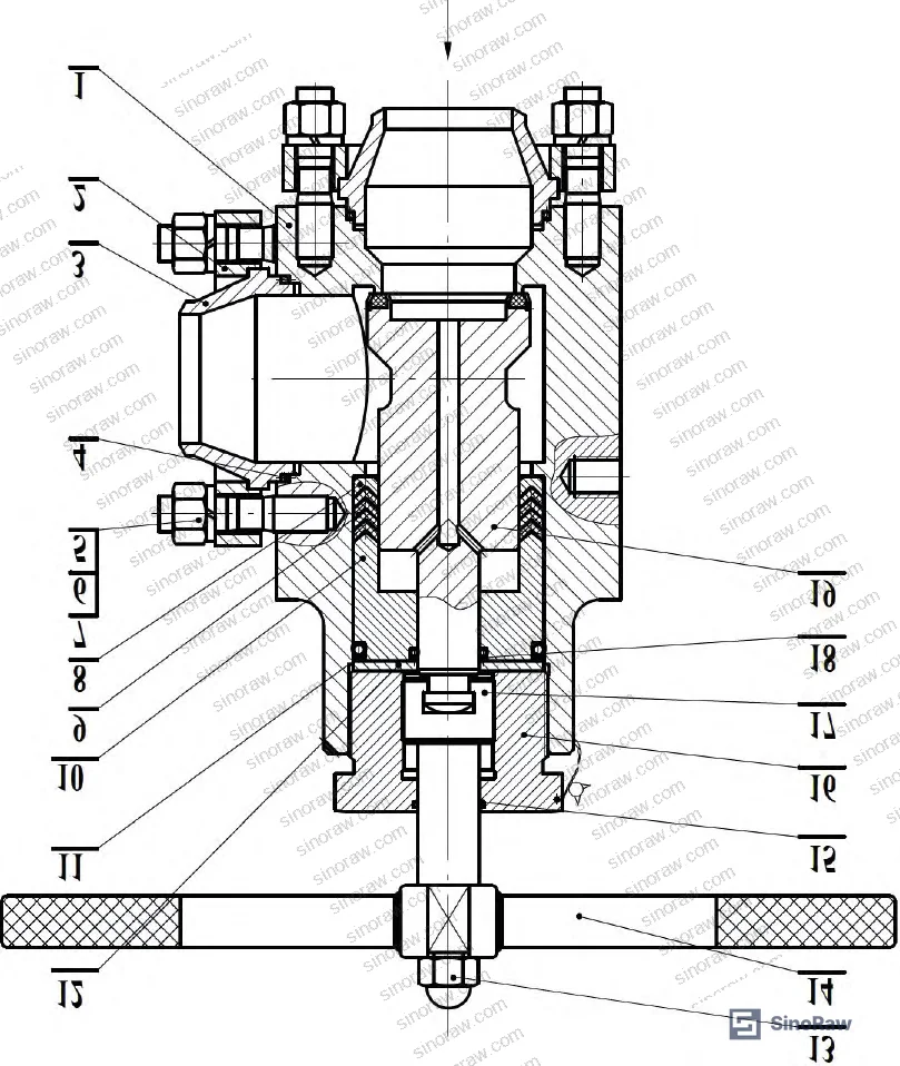
The findings have direct implications for anyone sourcing large-bore manual shut-off valves for high-pressure test systems, chemical processing lines, or any application where reliable open/close operation under corrosive, high-force conditions is non-negotiable. At sinoraw.com, we work with procurement engineers and sourcing managers who need to evaluate Chinese suppliers of exactly these components — and this type of failure analysis is precisely the technical basis on which supplier qualification decisions should be made.
Thread Jamming in High-Pressure Manual Globe Valves: Failure Mechanism and Root Cause #
This is where most procurement decisions go wrong: buyers specify pressure rating and material grade, but don’t interrogate the internal kinematic design of the valve stem-disc interface. The thread jamming failure documented here is a direct consequence of how the stem connects to the disc, not a material deficiency or a manufacturing quality issue in the conventional sense.
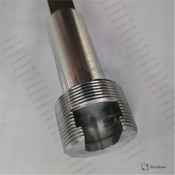
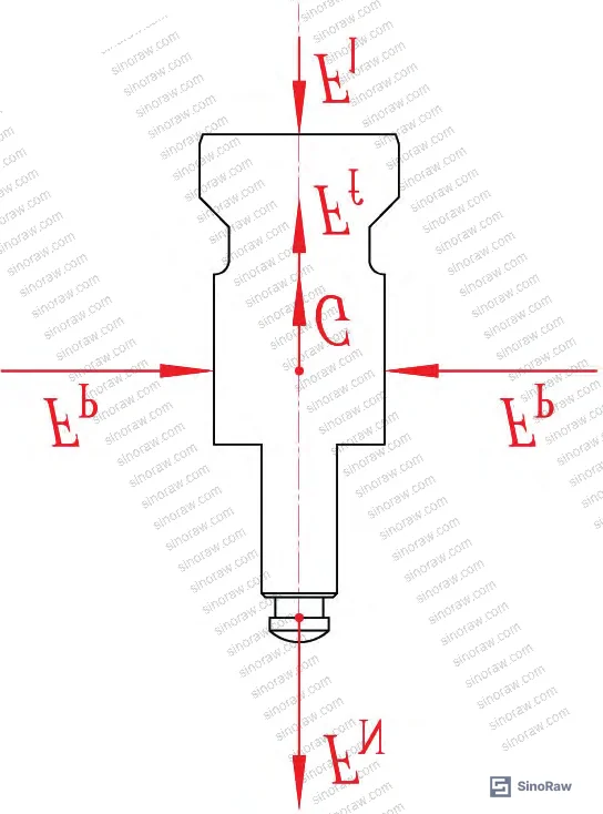
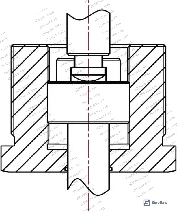
The kinematics of the problem. During valve operation, the stem rotates about its own axis while simultaneously translating axially. The disc assembly, by design, translates axially only — it does not rotate. The connection between stem and disc uses a U-shaped groove cut into the stem. This groove allows the disc to move axially while the stem rotates relative to it. The consequence: every open/close cycle generates sliding friction at the stem-disc contact interface, directly at the U-groove location.
In small-bore valves (DN≤20 mm — specifically DN6, DN8, DN10, DN15, and DN20 units from the same design family were examined and disassembled after extended service), this friction load is low enough that the original 14Cr17Ni2/PTFE material combination handles it without generating harmful debris. None of those small-bore units showed metal debris accumulation in the U-groove. The picture changes completely at DN50.
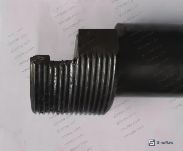
The force analysis. The lifting force the stem must exert on the disc during opening is governed by packing friction. For large-bore, high-pressure valves, the gland packing expands radially under axial compression — which is necessary to achieve adequate sealing — and that radial expansion generates substantial friction force against the disc. The friction force at the packing-disc interface scales with sealing contact pressure (p), packing inner diameter (d, approximately equal to valve bore), and packing height (h). At DN50 and PN12 MPa, these values produce contact forces at the stem-disc U-groove interface that exceed the material’s adhesive wear threshold. Under high normal load, real contact area increases, adhesive wear intensifies, and plowing wear from plastic deformation generates metal particles.
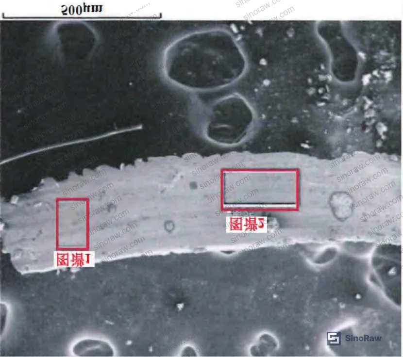
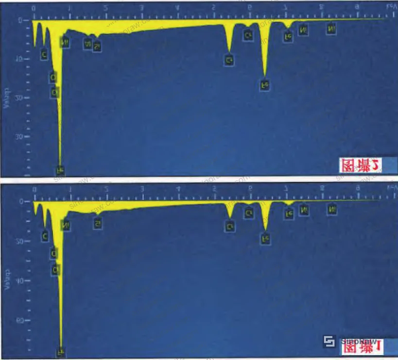
EDS analysis of debris recovered from jammed threads confirmed the composition: position 1 showed 72.73 wt% Fe, 16.44 wt% Cr, 2.42 wt% Ni, 7.34 wt% C, 0.78 wt% O, 0.30 wt% Si. Position 2: 71.95 wt% Fe, 17.24 wt% Cr, 2.01 wt% Ni, 7.24 wt% C, 1.0 wt% O, 0.37 wt% Si, 0.19 wt% Al. This is unambiguously consistent with 14Cr17Ni2 valve stem and disc material — ruling out contamination from assembly or external sources.
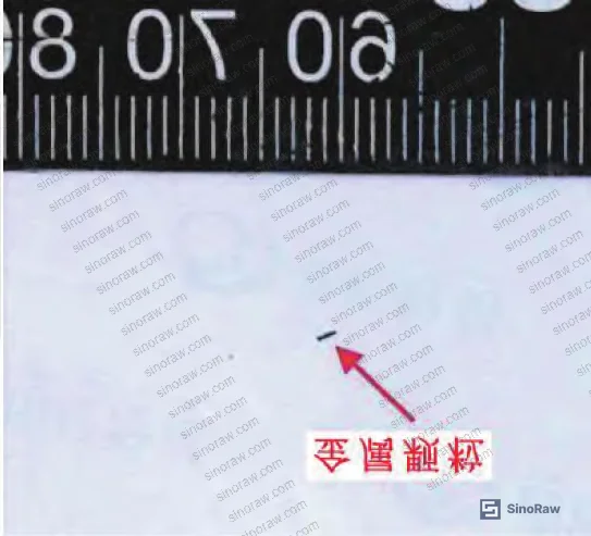
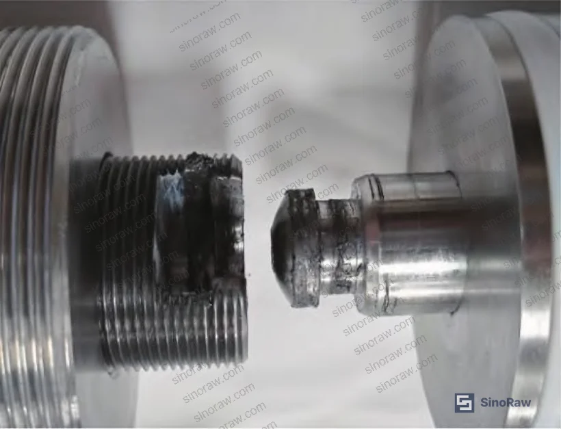
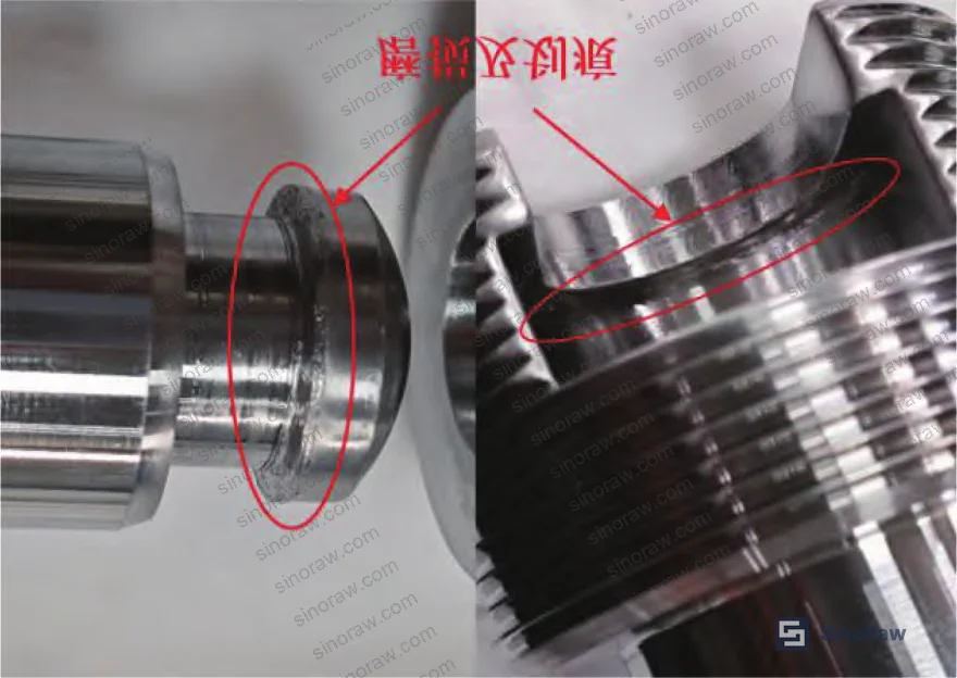
Three new valves were assembled clean, confirmed debris-free internally, and operated through repeated open/close cycles. Stiffening was observed at cycle 37, cycle 41, and cycle 58 respectively. Teardown revealed heavy debris accumulation in the U-groove lubrication grease in all three cases, with visible deep scratches at the stem-disc connection interface.
The critical design flaw: the U-groove was cut in the same axial zone as the drive thread. The groove interrupts thread continuity, creating open pathways for debris to migrate into thread engagement. Once debris enters the thread, it accumulates between flanks, causes plastic deformation of thread teeth, and ultimately seizes the thread entirely.
Structural Optimization of Manual Shut-Off Valve Drive Thread Systems #
The failure analysis points to four independent but complementary design changes. Any one of them reduces risk; the full set effectively eliminates thread jamming as a failure mode for this valve type and size range.
1. Relocate the U-groove below the drive thread zone. This is the highest-impact single change. By moving the U-groove lower on the stem and simultaneously reducing the stem diameter at the groove location, the groove cutout no longer intersects or disrupts the threaded engagement zone. Even if debris continues to be generated at the stem-disc interface, gravity carries it downward onto the lower packing seal rather than into the thread. The thread remains geometrically continuous.
2. Switch to wear-resistant materials at the friction interface. The original 14Cr17Ni2-on-14Cr17Ni2 stem/disc contact is the worst possible combination for adhesive wear — same alloy, same hardness, high galling tendency. The fix is straightforward: either substitute a harder or dissimilar material for one of the contact surfaces, or apply a wear-resistant coating (hard chrome, nitriding, or similar) to the contact zone. This reduces the volume of debris generated per cycle even before addressing the migration path.
3. Install a bearing at the stem-disc connection. Converting the sliding friction interface to rolling friction at the stem-disc junction essentially eliminates adhesive and abrasive wear at that location. With a bearing in place, the relative rotation between stem and disc is accommodated by rolling elements rather than direct metal-on-metal contact. This is the most mechanically robust solution for high-cycle applications.
4. Replace triangular thread with trapezoidal thread. Triangular (V-form) threads have sharp flanks and relatively low load-bearing cross-section — they are optimized for fastening, not for power transmission under sustained lateral and axial loading. Trapezoidal threads (similar to Acme thread form) have wider, flatter flanks, significantly higher contact area per pitch, greater resistance to debris-induced deformation, and better self-locking characteristics for valve stem applications. For a drive thread carrying the full opening/closing load of a DN50, PN12 MPa valve, the switch to trapezoidal geometry is not optional — it’s a correction.
Honestly, most buyers over-specify materials and under-specify thread geometry when writing valve procurement requirements. The instinct is to reach for exotic alloy grades; the actual leverage point in preventing this failure mode is thread form and groove location — neither of which appears on a standard material certificate.
For reference on applicable standards governing valve stem design and testing under these conditions, IEC 62619:2022 Safety requirements for secondary lithium cells and batteries is not directly applicable here, but buyers qualifying valves for fluid control in industrial energy systems should reference ISO 12405-4 Electrically propelled road vehicles — Test specification for lithium-ion traction battery packs and systems for broader system-level qualification context where these valves appear as BOP components. For general fluid control component testing methodology in critical systems, NFPA 855 Standard for the Installation of Stationary Energy Storage Systems provides relevant installation and component qualification guidance applicable to shut-off valve selection in stationary energy storage environments.
Comparison of original design versus optimized design across key parameters:
| Parameter | Original Design | Optimized Design |
|---|---|---|
| Thread form | Triangular (V-thread) | Trapezoidal |
| U-groove position | Within drive thread zone | Below drive thread zone (reduced stem diameter) |
| Stem-disc interface | Sliding friction, 14Cr17Ni2 on 14Cr17Ni2 | Rolling bearing / wear-resistant dissimilar material |
| Debris migration path | Direct access to thread flanks | Blocked — debris falls to lower packing seal |
| Observed jamming onset | Cycles 37, 41, 58 (3 of 3 test valves) | No jamming observed post-optimization |
| Applicable bore range | DN≤20 mm (acceptable), DN≥25 mm (failure prone) | DN≥25 mm (targeted correction) |
Most procurement teams don’t realize that thread form selection in valve stem design is treated as a secondary parameter in many Chinese valve manufacturer datasheets — it often defaults to whatever the shop floor tooling already has set up. If you don’t explicitly specify trapezoidal thread in your RFQ for large-bore manual globe valves, you will almost certainly receive triangular thread, and the failure mode described above becomes a matter of when, not if.
For buyers sourcing Fluid Control components through Chinese manufacturers, understanding this distinction between thread forms is essential qualification-stage knowledge. Related considerations around sealing system integrity in high-pressure valve assemblies also connect to broader Sealing & Thermal component selection — packing material choice directly affects the contact force that drives stem-disc interface wear.
Practical Guidance for Buyers #
If you’re buying DN≥25 mm manual globe valves for high-pressure service (PN≥12 MPa) and your application involves corrosive media, cyclic operation, or any requirement for repeatable positive shutoff, the failure mode described in this analysis should be your primary qualification screening criterion — not pressure rating, not material grade alone.
Start with the thread form. Ask explicitly: is the drive thread trapezoidal, and can you show me the thread specification in the drawing? Then ask about U-groove placement. A supplier who can tell you where the U-groove sits relative to the thread engagement zone — and why — is a supplier who has thought about this failure mode. One who can’t answer is one who hasn’t.
For corrosive media (oxidizing acids, strong oxidizers like N₂O₄), the stem and disc contact zone materials need to be explicitly qualified for wear resistance under the sealing loads your application generates. Don’t accept “stainless steel” as a complete answer — 14Cr17Ni2 against itself is a known galling risk, and the EDS data from this failure analysis confirms it generates significant metallic debris within 37–58 cycles.
On thread geometry: trapezoidal threads provide wider flanks, higher load-bearing cross-section, and substantially better debris tolerance than V-form threads. If a supplier can’t supply trapezoidal thread geometry in large-bore valve stems, that’s a design capability gap, not a minor specification difference.
At sinoraw.com, we help overseas procurement engineers identify and pre-qualify Chinese valve manufacturers against exactly this kind of technical specification — connecting buyers with verified suppliers before they issue RFQs, so qualification conversations start from a position of technical specificity rather than guesswork. If your current supplier pool can’t answer these questions, that’s a sourcing problem we can help resolve.
Need help identifying qualified suppliers for large-bore high-pressure manual globe valves? Talk to our sourcing team →
Supplier Qualification Questions #
- Where is the U-groove positioned on the valve stem relative to the drive thread engagement zone — is it within the threaded section or displaced below it, and what is the stem diameter reduction at the groove location?
- What is the drive thread form used in your DN≥25 mm manual globe valve stems — triangular or trapezoidal — and can you provide the thread specification drawing confirming flank angle and pitch?
- What wear-resistant material or surface treatment is applied at the stem-disc sliding contact interface for valves rated PN≥12 MPa, and what is the hardness differential between the stem and disc contact surfaces?
- Have your DN50 large-bore globe valve designs been subjected to cyclic operation testing, and at what cycle count did any stiffening or thread anomalies first appear in your test records — specifically for the stem drive thread?
- Can you provide EDS or equivalent compositional analysis confirming the absence of metallic debris accumulation in the U-groove region after a defined number of operational cycles (e.g., ≥50 open/close cycles) under rated pressure?
Sourcing Checklist #
- ☐ Drive thread form is confirmed as trapezoidal (not triangular/V-thread) for all valve stems at DN≥25 mm
- ☐ U-groove is positioned below the drive thread engagement zone, with reduced stem diameter at the groove to prevent direct debris-to-thread migration
- ☐ Stem and disc contact materials are dissimilar alloys or one surface carries a wear-resistant coating; same-alloy pairing (e.g., 14Cr17Ni2 on 14Cr17Ni2) is flagged for review
- ☐ Supplier provides cyclic operation test data showing no thread stiffening or jamming before ≥50 open/close cycles at rated pressure (PN≥12 MPa)
- ☐ For corrosive media service (oxidizing acids, N₂O₄), stem material corrosion resistance is separately verified — material certificate specifying 14Cr17Ni2 or equivalent martensitic stainless grade is present
- ☐ Internal cleanliness inspection records confirm no metallic debris inside valve cavities prior to final assembly (assembly area cleanliness protocol documented)
- ☐ For high-cycle or critical shutoff applications, bearing installation at the stem-disc connection interface is either standard or available as a specified option
Key Specifications Table #
| Parameter | Recommended Value | Verification Method |
|---|---|---|
| Drive thread form (DN≥25 mm stem) | Trapezoidal | Engineering drawing review; thread gauge inspection |
| U-groove axial position | Below drive thread zone (outside thread engagement length) | Cross-section drawing; dimensional inspection of stem |
| Stem-disc interface material pairing | Dissimilar alloys or wear-resistant coating (hardness differential ≥50 HV recommended) | Material certificate + hardness test report |
| Cyclic jamming-free operation | ≥50 open/close cycles at PN12 MPa with no thread stiffening | Cyclic operational test report with cycle log |
| Metal debris in U-groove | Zero metallic particulate in grease/lubricant after test cycles | EDS analysis or visual inspection post-teardown |
| Operating temperature range | −40 to +50°C | Design specification / material qualification data |
| Nominal bore for critical design review | DN≥25 mm (DN≤20 mm lower risk; DN≥25 mm requires optimized design) | Confirmed by bore measurement and design classification |
Can’t find a supplier meeting these specs? Submit your requirements and we’ll match you within 48 hours.
References #
Data source: Failure Analysis and Structural Optimization of Drive Thread Seizure in Large-Bore High-Pressure Manual Globe Valves, Y.-L. Tang et al., Journal of Mechanical Engineering and Industrial Applications, 2023
Frequently Asked Questions #
Why does thread jamming occur in large-bore valves but not in small-bore valves of the same design family?
The root cause is force scaling. Packing friction against the disc assembly increases with both sealing contact pressure and bore diameter — so at DN50 and PN12 MPa, the contact force at the stem-disc U-groove interface is substantially higher than at DN20 or smaller. Small-bore units (DN6 through DN20) from the same design family were disassembled after extended service and showed no metallic debris accumulation and no wear damage. The material combination that’s adequate at small bore becomes a galling risk at large bore because the contact loads exceed the adhesive wear threshold.
What does EDS analysis of the debris actually tell you, and why does it matter for qualification?
EDS (energy-dispersive spectroscopy) confirms the elemental composition of debris particles. In this case, debris at positions 1 and 2 showed iron, chromium, and nickel content consistent with 14Cr17Ni2 stainless steel — ruling out external contamination and confirming the particles came from internal wear at the stem-disc interface. For buyers, this matters because it tells you the failure is design-driven, not assembly-quality-driven. You can’t inspect your way out of it; you need a different design.
Is replacing the thread form from triangular to trapezoidal enough on its own to prevent jamming?
It helps, but it’s not sufficient as a standalone fix. Trapezoidal threads are more debris-tolerant and have higher load-bearing cross-section, which delays failure onset. But if the U-groove remains positioned within the drive thread zone, debris migration into the thread continues regardless of thread form. The two changes that have to happen together are: (1) relocate the U-groove, and (2) change the thread form. Adding wear-resistant materials and a bearing at the stem-disc interface provides additional margin for high-cycle applications.
How do I know if a valve I’m already using has this design flaw?
Request the valve stem assembly drawing and look at two things: where the U-groove sits relative to the drive thread, and what the thread form is. If the U-groove intersects the thread zone and the thread is triangular, the design has the failure preconditions described here. You can also ask the supplier for their recommended maximum cycle count before maintenance — if they don’t have one or it’s vague, that’s a signal they haven’t done the failure analysis.
Does this failure mode apply to automated (actuated) globe valves as well?
The core mechanism — stem-disc sliding friction generating debris that migrates into the drive thread — applies to any globe valve where the stem rotates while the disc translates, regardless of whether it’s manually or actuator-driven. Actuated valves may cycle far more frequently, which would accelerate debris accumulation. The structural fixes (U-groove relocation, trapezoidal thread, bearing installation, wear-resistant materials) are equally applicable to motorized or pneumatic actuator configurations at DN≥25 mm, PN≥12 MPa.
Published by sinoraw.com Technical Team | Request a sourcing quote


