

TL;DR #
Across 24 nuclear island units, hard-seal globe valves operating on a 6-cycle (6C) preventive disassembly schedule showed a corrective maintenance incidence of only 1.35% — confirming that the majority of scheduled teardowns are unnecessary under current operating conditions. For industrial buyers specifying hard-seal globe valves in high-pressure, high-temperature isolation service, this data means over-specifying maintenance frequency carries measurable cost and radiation dose penalties without a corresponding reliability gain. Qualify suppliers by demanding Weibull reliability modeling data and bench test results at ≥21.40 MPa / 350°C before accepting any valve for critical isolation duty.
Overview #
If your procurement team is still treating hard-seal globe valve maintenance intervals as a fixed, conservative default, recent reliability engineering data from multi-unit nuclear island fleet analysis should prompt a serious re-evaluation. A systematic study covering 150 hard-seal globe valves across seven nuclear island systems — RCP, RIS, RCV, REA, REN, PTR, and RPE — applied FMEA classification, Weibull reliability modeling, and bench-test verification to quantify exactly how much service margin these valves carry beyond their scheduled teardown points. The work was conducted by a national nuclear safety and reliability engineering research center, and the dataset includes both operational failure records and preventive maintenance truncation data pooled across 24 comparable reactor units. The findings are directly applicable to any high-consequence fluid isolation application, not just nuclear — the valve construction, failure modes, and material interactions are identical to what you encounter in high-pressure chemical, refinery, and power generation service.
The structural baseline matters here: these valves use bellows seal + packing seal configurations, Stellite alloy seat and disc faces, stem and bearing lubrication ports, and handle media ranging from low-concentration boric acid to demineralized water at design pressures up to 17.13 MPa and temperatures up to 343°C. That is not a gentle operating envelope, which makes the reliability data all the more credible as a benchmark for industrial specification.
For procurement teams sourcing through Chinese manufacturers, SinoRaw operates as a Guangzhou-based B2B sourcing and supplier qualification service — our role is to help overseas engineers identify and vet Chinese valve manufacturers before RFQs are issued, not to manufacture valves ourselves. The specification thresholds and test criteria in this article are directly usable as supplier qualification benchmarks.
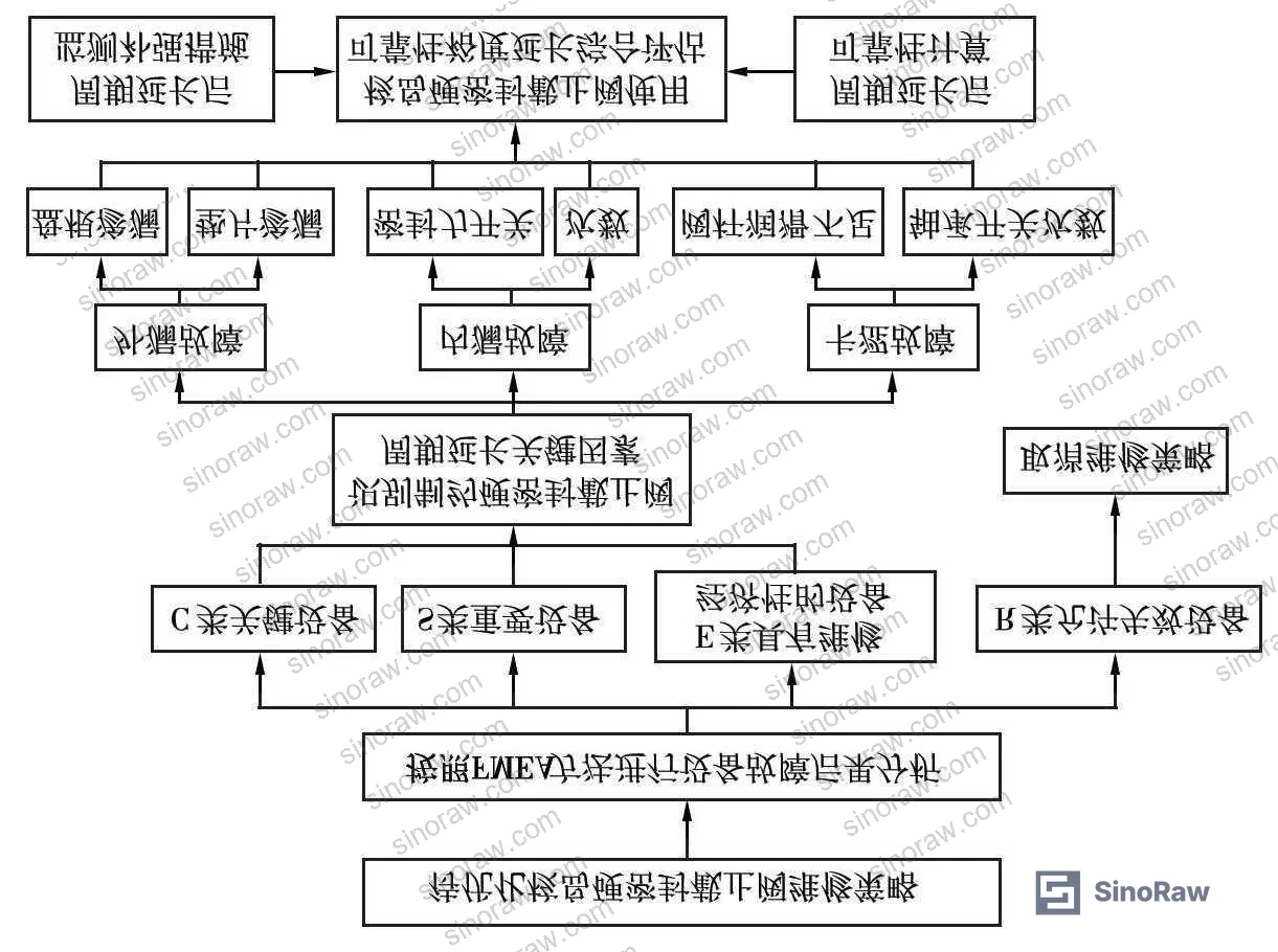
Hard-Seal Globe Valve Failure Mode Classification and Criticality Grading #
The 150 valves in the study fleet were sorted into four criticality tiers using FMEA methodology applied from system design intent outward:
- C-class (Critical): Failure immediately degrades nuclear safety or unit availability. Consequence is unacceptable.
- S-class (Safety-significant): Failure does not immediately degrade safety but increases unsafe event probability or risk of major equipment damage.
- E-class (Economic): Failure has no safety consequence, but preventive maintenance cost is lower than run-to-failure cost.
- R-class (Run-to-failure permitted): Failure has no nuclear safety or availability consequence. Preventive maintenance is not required.
The classification outcome was decisive: 109 of 150 valves — 72.7% of the fleet — were graded R-class. Their scheduled periodic inspection and disassembly programs were eliminated entirely, replaced by routine walk-down surveillance with corrective response on finding. The remaining 41 valves (C + S + E combined) retained preventive disassembly programs, but became the subject of service life extension analysis from a 10-year to a 15-year overhaul interval (expressed as 6C to 9C in reactor fuel cycle units).
| Valve Class | Failure Consequence | Fleet Count | Maintenance Approach |
|---|---|---|---|
| C (Critical) | Immediate nuclear safety / availability degradation | Subset of 41 | Retain PM + add 3C diagnostic |
| S (Safety-significant) | Increased unsafe event probability | Subset of 41 | Retain PM, extend to 9C |
| E (Economic) | No safety impact; PM cost < run-to-failure cost | Subset of 41 | Retain PM, extend to 9C |
| R (Run-to-failure) | No safety or availability impact | 109 | Cancel PM; corrective only |
Honestly, most procurement teams over-classify valve criticality by default — it feels safer to schedule more teardowns. What this dataset demonstrates is that two-thirds of a tightly regulated nuclear island valve fleet can safely move to run-to-failure management without any measurable reliability penalty. In commercial industrial applications where the safety envelope is less demanding, the fraction that genuinely needs scheduled disassembly is probably even smaller.
The six identified failure modes and their time-dependency status are the foundation for any interval optimization argument. Time-related failure modes — compression set of packing and gaskets, packing wear against the stem, bellows fatigue cracking, sealing face wear, and bearing lubrication depletion — are the ones that actually drive disassembly intervals. Random failure modes — packing bore scratching, chloride-induced packing corrosion, boric acid attack on sealing faces, thermal stress deformation of disc/seat, and stem seizure from foreign debris — do not benefit from scheduled teardown and should be managed by surveillance and condition monitoring instead.
Reliability Testing and Service Life Extension: 6C to 9C Margin Verification #
The service life extension argument rests on four parallel lines of evidence: failure mode analysis, worst-case operating parameter benchmarking, cross-fleet operational data, and accelerated bench testing.
Worst-case operating parameter baseline (Valve A): The most severe combination of parameters from all C/S/E-class valves was consolidated into a single reference envelope:
| Parameter | Worst-Case Value |
|---|---|
| Maximum design pressure | 17.13 MPa |
| Maximum design temperature | 343°C |
| Maximum operating cycles per outage | 35 |
| Maximum sealing surface contact stress | 245 MPa |
| Process medium | Low-concentration boric acid |
The calculated maximum sealing surface contact stress of 245 MPa comes from the standard sealing pressure formula that accounts for sealing face load, hydrostatic pressure, sealing force, face inner diameter, and face width. This figure is the key wear driver — the higher the contact stress and the more open/close cycles accumulated, the faster surface roughness degrades toward internal leakage.
Bench test validation (Test Valve B): To verify that the 6C→9C extension is achievable, a test valve of identical construction but intentionally more severe specifications was tested: design temperature 350°C (vs. 343°C for Valve A) and design pressure 21.40 MPa (vs. 17.13 MPa for Valve A) — both parameters exceeding the actual service envelope.
The test protocol and acceptance criteria are summarized below:
| Test Phase | Conditions | Acceptance Criterion | Result |
|---|---|---|---|
| Cold-state cycling | Room temp, 21.4 MPa water, 1800 open/close cycles | No visible external leakage; stem seal area dry | Pass |
| Valve seal test | Room temp, A-class water, 37 MPa hydrostatic, ≥10 min hold | Leakage ≤ 0.027 mL/min | Pass |
| Packing seal test | Room temp, A-class water, 33.7 MPa, ≥5 min hold | No visible leakage at packing top | Pass |
| Hot-state cycling | 350°C, 21.40 MPa water, 1650 open/close cycles | No visible external leakage; open/close normal | Pass |
Test Valve B passed all four test phases — internal and external leakage both within limits — despite operating at pressure and temperature conditions harder than any valve in the actual service fleet. This is the bench-test anchor for the extension argument: if a valve at 21.40 MPa / 350°C can complete 1800 + 1650 cycles without failure, then Valve A at 17.13 MPa / 343°C can reasonably be expected to maintain acceptable reliability through a 9C interval.
In supplier qualification, we have seen situations where valve manufacturers present sealing certification data obtained under mild test conditions that do not bracket actual service parameters. The test-harder principle demonstrated here — testing at conditions that envelope the worst-case service valve, not just match it — is the right methodology to demand from any supplier offering extended-interval maintenance claims.
Cross-fleet operational data: Across 24 similar reactor units executing 592 instances of 6C preventive disassembly, only 8 corrective disassembly events occurred during the operating windows. That is a 1.35% corrective incidence rate. With fault count greater than 5, the dataset qualifies for classical Weibull parameter estimation using maximum likelihood.
Weibull reliability quantification: Using a two-parameter Weibull model applied to the operational failure and PM truncation data, the calculated failure probability increase from extending the interval from 6C to 9C is only 0.66 percentage points. That is the quantified reliability cost of the extension. For C-class valves, this small degradation is compensated by adding a 3C periodic electric actuator diagnostic (covering actuator head + valve body), matching the existing 3C actuator maintenance cycle.
Most procurement teams don’t realize that reliability-based maintenance interval optimization for industrial valves has been standard practice in nuclear operations for over a decade — yet the same quantitative methods are rarely applied to identical valve populations in chemical, refinery, or power generation procurement contracts. If your current valve PM interval was set by the original equipment specification without a fleet-data review, it is almost certainly conservative by at least one maintenance cycle.
For guidance on relevant international standards governing valve testing in energy and process applications, IEC 62619:2022 Safety requirements for secondary lithium cells and batteries establishes comparable principles for reliability and safety validation in high-consequence energy systems. For fluid system component qualification methodology, ISO 12405-4 Electrically propelled road vehicles — Test specification for lithium-ion traction battery packs and systems provides a useful parallel framework for systematic parameter envelope testing. Buyers working with valve systems in power generation environments should also consult NFPA 855 Standard for the Installation of Stationary Energy Storage Systems for co-installed system requirements.
Economic Benefit Calculation and Maintenance Cost Recovery #
The extension from 6C to 9C across 150 hard-seal globe valves in a single nuclear unit produces savings that are conservative and auditable over a 60-year plant life:
- Each valve undergoes 2 fewer disassembly overhauls over the 60-year service life
- Radiation dose reduction: approximately 18 person·mSv per valve across the life cycle
- Total maintenance cost savings (spare parts + labor): approximately 730,000 RMB per unit
These figures use conservative assumptions. The actual benefit scales with labor rates, spare part pricing, and dose management overhead — all of which tend to be higher for critical-service components.
Beyond cost, the extension reduces over-maintenance risk. Every unnecessary disassembly is a reliability event in itself — it introduces re-assembly variability, potential for introduced contamination, and reseating uncertainty on Stellite faces. Reducing teardown frequency on valves that do not need it is not just an economic optimization; it is a reliability improvement.
For procurement teams sourcing Fluid Control components from Chinese manufacturers, or evaluating vendors who supply Sealing & Thermal materials used in these valve assemblies, the lesson is direct: demand that your supplier can produce both the reliability data justifying their recommended maintenance interval and the bench test results showing their test conditions enveloped — not merely matched — the service specification.
Practical Guidance for Buyers #
If you are sourcing hard-seal globe valves for high-pressure isolation service — nuclear, chemical, or power generation — the key procurement errors to avoid are over-classifying valve criticality and accepting maintenance intervals that were set by conservative default rather than data.
Start by requiring suppliers to provide FMEA-based classification evidence for the specific valve population you are buying. A supplier who cannot distinguish time-dependent failure modes (packing wear, face wear, bellows fatigue, lubrication depletion) from random failure modes (corrosion, thermal deformation, debris damage) is not equipped to recommend a defensible maintenance interval.
On sealing performance, the 245 MPa maximum contact stress calculated from the worst-case service fleet is a useful benchmark. Any valve offered for comparable service should have sealing test data at or above this contact stress level. Similarly, the 33.7–37.0 MPa hydrostatic hold test with leakage ≤ 0.027 mL/min is the acceptance standard you should be writing into your purchase specification.
For Stellite-faced disc and seat assemblies, ask specifically about surface roughness degradation curves as a function of open/close cycles and contact stress. Suppliers who can provide this data have done the engineering work; those who cannot are relying on legacy design margins they cannot quantify.
SinoRaw connects overseas procurement engineers with verified Chinese manufacturers of industrial valve components and sealing materials — our sourcing team can help you identify suppliers capable of producing this level of technical documentation before you issue an RFQ.
Need help identifying qualified suppliers for hard-seal globe valves or nuclear-grade sealing components? Talk to our sourcing team →
Supplier Qualification Questions #
- Can you provide FMEA failure mode classification data showing which failure modes in your hard-seal globe valves are time-dependent versus random, and what percentage of your fleet analysis falls into each category?
- What is the maximum sealing surface contact stress (in MPa) your valves are rated to, and can you show the calculation basis using the sealing pressure formula accounting for face load, hydrostatic force, sealing force, face inner diameter, and face width — with a demonstrated minimum of 245 MPa for critical-service valves?
- Can you provide bench test results where the test valve was operated at conditions exceeding the service specification — specifically at pressure ≥ 21.40 MPa and temperature ≥ 350°C — with leakage results showing ≤ 0.027 mL/min under 37 MPa hydrostatic hold for at least 10 minutes?
- What is the documented maximum open/close cycle count per maintenance interval for your valves, and do you have fatigue data on your bellows assemblies showing the number of cycles to first failure at rated pressure and temperature?
- Can you supply two-parameter Weibull reliability model outputs — derived from a fleet of at least 24 comparable units with more than 5 confirmed failure events — showing the failure probability increase associated with extending the maintenance interval by 1.5× beyond your standard recommendation?
Sourcing Checklist #
- ☐ Supplier provides FMEA-based valve criticality classification separating C/S/E/R classes with documented failure consequence criteria for each tier
- ☐ Valve sealing face material confirmed as Stellite alloy (cobalt-chromium) with surface roughness specification and degradation data across the rated open/close cycle count
- ☐ Bench test report shows test conditions at ≥ 21.40 MPa and ≥ 350°C enveloping the service specification, not merely matching it
- ☐ Leakage test results confirm ≤ 0.027 mL/min under 37 MPa hydrostatic hold at ≥ 10-minute duration for valve seal, and zero visible leakage at packing top under 33.7 MPa for ≥ 5 minutes
- ☐ Packing and gasket materials (316L wire-braided flexible graphite, flexible graphite + carbon fiber) confirmed with no mandatory replacement interval and compression set data available
- ☐ Supplier can demonstrate maximum sealing contact stress ≥ 245 MPa based on calculated sealing parameters for the worst-case service condition
- ☐ Supplier holds operational failure data from ≥ 20 comparable valve units with corrective maintenance incidence rate documented (benchmark: ≤ 1.35% over multiple scheduled inspection cycles)
- ☐ For electrically actuated variants: 3C periodic actuator diagnostic (actuator head + valve body combined) is included in the maintenance program documentation
Key Specifications Table #
| Parameter | Recommended Value | Verification Method |
|---|---|---|
| Maximum design pressure | ≥ 17.13 MPa (service); test valve qualified at ≥ 21.40 MPa | Hydrostatic pressure test per supplier test report; 37 MPa hold ≥ 10 min |
| Maximum design temperature | 343°C (service); test validated at 350°C | Thermocouple-monitored hot-state cycling test at rated pressure |
| Maximum sealing surface contact stress | ≥ 245 MPa | Calculated from sealing pressure formula: face load, hydrostatic force, sealing force, inner diameter, face width |
| Leakage acceptance limit | ≤ 0.027 mL/min (valve seal); zero visible leakage (packing) | A-class water, room temperature, 37 MPa hold ≥ 10 min; 33.7 MPa hold ≥ 5 min |
| Maximum open/close cycles per maintenance interval | ≤ 35 per outage (service); test validated at 1800 cycles cold + 1650 cycles hot | Cycle counter log; hot-state test at 350°C / 21.40 MPa |
| Corrective maintenance incidence rate | ≤ 1.35% over rated PM interval | Fleet statistical analysis from ≥ 20 comparable units; failure data with classical Weibull estimation where n ≥ 5 |
| Reliability degradation from interval extension (6C → 9C) | Failure probability increase ≤ 0.66% | Two-parameter Weibull maximum likelihood estimation from operational failure and PM truncation data |
Can’t find a supplier meeting these specs? Submit your requirements and we’ll match you within 48 hours.
References #
Data source: Reliability-Based Maintenance Interval Optimization for Hard-Seal Globe Valves in Nuclear Island Fluid Systems, W.-D. Song et al., Nuclear Engineering and Design, 2024
Frequently Asked Questions #
What is a hard-seal globe valve and why does the sealing face material matter so much?
A hard-seal globe valve uses metal-to-metal contact between the disc (valve plug) and seat for sealing — typically Stellite alloy, a cobalt-chromium material chosen for hardness, corrosion resistance, and ability to maintain surface finish under repeated mechanical loading. The sealing face material determines how quickly surface roughness degrades with each open/close cycle. As roughness increases, the contact sealing pressure required to prevent internal leakage must also increase, or leakage begins. In the study fleet operating at up to 245 MPa contact stress and 343°C, Stellite faces remained serviceable beyond 9 fuel cycles without refurbishment — which is the core finding that enables interval extension.
What does “6C to 9C” mean in practical maintenance scheduling terms?
C refers to a reactor fuel cycle, typically 18 months in duration. So 6C = approximately 9 years between scheduled disassembly overhauls, and 9C = approximately 13.5 years. The extension being analyzed is not a minor adjustment — it eliminates two full teardown events per valve over a 60-year plant life.
How do I know if a valve supplier’s maintenance interval recommendation is supported by data or just conservative default?
Ask for fleet operational failure data from at least 20 comparable units covering the proposed maintenance interval. The benchmark from this dataset is a 1.35% corrective maintenance incidence rate across 592 instances of 6C inspections. If a supplier cannot provide population-level failure data with Weibull parameter estimates, their recommended interval is likely based on design margins set at commissioning, not on operational evidence. That is not necessarily unsafe, but it probably means you are over-maintaining.
What failure modes should I monitor if I extend valve maintenance intervals?
The three time-dependent failure modes to watch are internal leakage (sealing face wear), external leakage (packing wear and gasket compression set), and stem/bearing sticking (lubrication depletion). For valves extended to longer intervals, add periodic condition monitoring: for electrically actuated valves, a 3C actuator diagnostic (torque signature + valve body response) provides early warning of developing sticking or internal leakage before the next scheduled teardown. Random failure modes — corrosion, thermal deformation, debris damage — are not addressed by more frequent disassembly and should be managed through fluid chemistry control and surveillance.
Can the maintenance interval optimization methodology described here be applied to non-nuclear industrial valves?
Yes, directly. The FMEA classification framework, Weibull reliability modeling approach, and bench test validation methodology are standard reliability engineering tools that apply to any valve population with sufficient operational history. The nuclear context provides a demanding test case — high pressure, high temperature, corrosive media, strict leakage limits — but the analysis structure is transferable to refinery, chemical processing, and power generation valve fleets operating under comparable conditions. The minimum requirement is having failure data from at least 5 events in a comparable population to apply classical Weibull estimation.
Published by sinoraw.com Technical Team | Request a sourcing quote


