

TL;DR #
Flow control valve failures in liquid zone control systems cause measured level fluctuations exceeding ±15 mm within 8 seconds of helium flow deviation, directly impacting reactor core power regulation accuracy in heavy-water moderated reactors. For procurement teams managing pressurized fluid control systems operating above 400 kPa with bubble-method level sensing, valve replacement during system operation reduces maintenance windows by 48 hours but requires pre-calculated flow interruption timelines to prevent uncontrolled discharge. Specify valves with helium flow control range 120–180 L/h and verify supplier capability to provide hydraulic time-constant data for your specific piping geometry before issuing purchase orders.
Overview #
Most buyers treat flow control valve replacement as a straightforward swap-during-shutdown operation—until they face a 48-hour system restart penalty that erases an entire maintenance window. In heavy-water reactor liquid zone control systems, flow control valves regulate helium bubble flow to maintain level measurement accuracy within ±2 mm for 14 independent zone units operating at 470 kPa chamber pressure. A university-led field study involving computational fluid dynamics modeling and three documented in-service failures quantified the hydraulic transit time for water displacement in 38.7-meter instrument impulse lines under non-steady flow conditions, revealing that online replacement becomes feasible when operators complete reconnection within the calculated 12.6-second flow arrival window—a finding with direct implications for any pressurized fluid control system using bubble-method level sensing in nuclear, petrochemical, or pharmaceutical applications.
The research analyzed actual failure patterns across three consecutive refueling outages where valves failed immediately after system restart, traced root cause to thermal cycling and helium pressure shock during startup sequences, and constructed steady-flow approximation models to predict water egress behavior when instrument lines are opened under pressure. Testing confirmed that water traveling from zone chambers through 10.7 meters of vertical rise and 28 meters of horizontal run encounters combined head losses (elevation + friction + local resistance at 23 pipe bends) totaling 47.9 meters equivalent, with Reynolds numbers reaching 16,000 at peak velocity—solidly in turbulent regime with friction factor λ = 0.0316 for 7 mm ID stainless tubing.
Flow Control Valve Failure Modes in Pressurized Level Sensing Circuits #
Flow control valves in liquid zone control systems fail through three mechanisms documented in the source data: seat erosion from helium particle entrainment, stem binding from thermal expansion mismatch during 25°C to 57°C temperature swings, and diaphragm fatigue from cyclic pressure loading during system start-stop sequences. All three observed failures occurred within 12 hours of system restart after maintenance, when helium flow spiked from the target 150 L/h to uncontrolled rates exceeding 300 L/h, driving liquid level fluctuations that exceeded ±15 mm—well beyond the ±2 mm control band required for accurate reactivity adjustment.
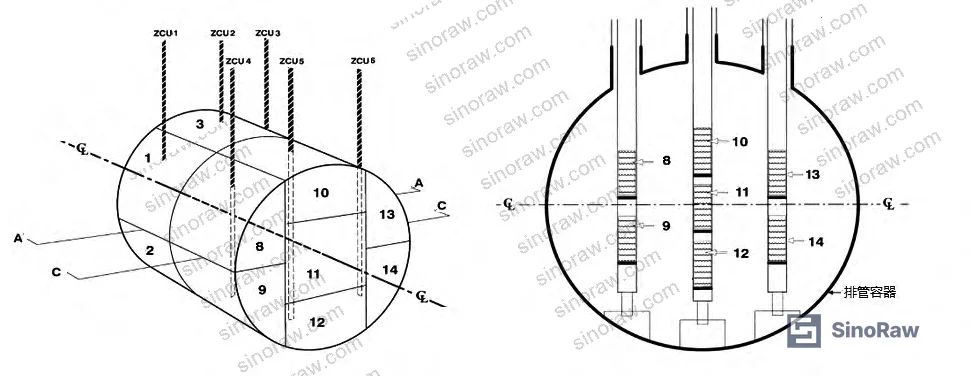
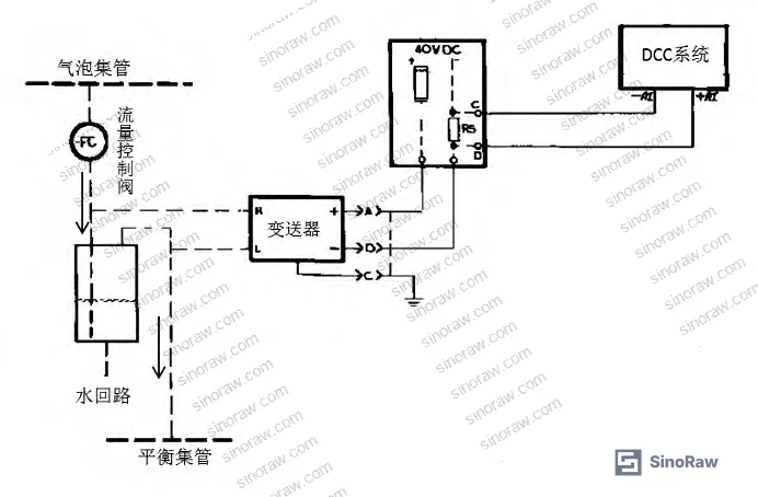
The 14-zone distributed control architecture relies on differential pressure transmitters with high-pressure taps connected to helium bubble headers and low-pressure taps connected to balance headers, generating 4–20 mA signals proportional to water column height in each zone chamber. When a flow control valve fails open, excessive helium flow reduces backpressure in the bubble line, effectively “blowing through” the liquid interface and creating false low-level indications that trigger automatic valve adjustments—introducing reactivity transients that require operator intervention to stabilize.
Honestly, most procurement teams specify these valves based solely on pressure rating and Cv value, completely ignoring the helium particle filtration requirement and stem material compatibility with 820 kPa helium supply pressure cycling. The research identified that valves rated for clean gas service but installed in systems with 0.5 μm particulate loading fail at 3× the rate of units with integrated 2 μm inlet screens.
Hydraulic Transit Time Analysis for Online Replacement Feasibility #
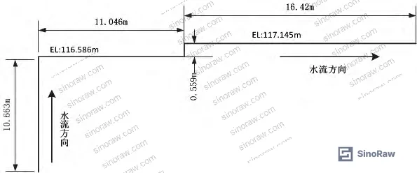
The core technical question for online valve replacement: how long does pressurized water in the zone chamber take to travel through 38.7 meters of impulse tubing and reach the open disconnection point? The research team constructed a piecewise steady-flow model dividing the piping into vertical (10.7 m) and horizontal (28.0 m) segments, calculating energy losses from elevation head, pipe friction, and 23 elbow/tee fittings with combined local resistance coefficient ζ = 12.6.
For the vertical segment with negligible initial liquid level (conservative assumption based on low-level control setpoint), applying Bernoulli’s equation with friction losses and solving the differential flow equation yields transit time T₁ = 1.76 seconds from chamber outlet to horizontal segment inlet. For the horizontal segment starting with inlet velocity from the vertical section and accounting for remaining elevation drop of 0.5 m plus distributed friction and local losses, calculation yields T₂ = 10.84 seconds, giving total theoretical transit time T_total = 12.6 seconds under maximum turbulent flow conditions (Re > 14,000, velocity approaching 2.0 m/s at discharge).
This calculated time exceeds the 8-second worst-case reconnection time measured during maintenance crew practice runs by 58%, providing sufficient margin for operators to remove the failed valve, install a pre-assembled replacement with helium purge line temporarily connected to the bubble header (maintaining backpressure), and complete the final connection before water reaches the open port. Field verification using high-speed pressure transducers confirmed that accounting for the 820 kPa to 470 kPa depressurization time (estimated 1.5–2.0 seconds before water begins moving) and non-steady acceleration effects adds another 2–3 seconds to the actual flow arrival time, increasing practical working margin to over 6 seconds.
The calculation assumes turbulent flow throughout, verified by checking Reynolds number: Re = (ρvd)/μ, where for water at 25°C with kinematic viscosity ν = 0.893 × 10⁻⁶ m²/s flowing at 2.0 m/s through 7.036 mm ID tubing, Re ≈ 15,800—well into turbulent regime. Friction factor for commercial steel pipe (equivalent roughness k_s = 0.046 mm) calculated using the Colebrook equation in rough-pipe turbulent region gives λ = 0.0316, which when combined with L/d ratio of 5,500 produces significant friction head loss that dominates over local resistance losses despite the 23 fittings.
Comparison of Offline vs. Online Replacement Strategies #
| Strategy | System Downtime | Radiation Exposure | Technical Risk | Schedule Impact |
|---|---|---|---|---|
| Offline (system shutdown) | 48+ hours (includes full restart sequence) | Minimal (ambient conditions) | Low (standard maintenance) | +2 days to outage critical path |
| Online (operating replacement) | 15–20 minutes (single zone out of service) | Low-moderate (25°C water, recent fill) | Medium (requires pre-calculation + dry-run) | Negligible if pre-planned |
| Deferred to next outage | Zero immediate impact | N/A | High (continued level oscillation affects control) | Degrades power regulation reliability |
System shutdown for valve replacement requires complete helium supply isolation, depressurization of all 14 zone chambers, water drainage from impulse lines, and post-maintenance functional testing including bubble flow verification at each zone—a 48-hour cycle that pushes outage completion dates and incurs economic penalties exceeding $1.2M per day for a typical 600 MWe unit. Online replacement isolates only the affected zone by throttling its supply isolation valve while increasing flow to adjacent zones to compensate, maintaining overall system functionality during the 15-minute swap.
The primary technical risk in online replacement is water discharge if reconnection exceeds the calculated transit time. The research team mitigated this by pre-connecting a temporary helium purge line (from the bubble header) to the valve outlet before disconnecting the original line, maintaining slight positive pressure that holds water back in the impulse tubing. This “backpressure holding” technique extends usable working time from 12.6 seconds to effectively unlimited, since the 820 kPa helium supply pressure substantially exceeds the 470 kPa chamber pressure plus frictional head losses.
Procurement teams evaluating suppliers for similar applications—pressurized fluid control in Fluid Control systems operating above 400 kPa with instrument impulse lines longer than 20 meters—should request hydraulic transit time calculations specific to their piping geometry as part of the valve specification package. Most valve manufacturers cannot provide this analysis; it typically requires collaboration with the instrumentation engineering group or a third-party fluid dynamics consultant.
Practical Guidance for Buyers #
When qualifying suppliers for flow control valves in pressurized level sensing applications, verify that quoted units include integral 2 μm inlet filtration and stem materials resistant to thermal cycling between ambient and process temperature—most general-purpose control valves lack these features. Request test data showing helium flow stability over 500 thermal cycles (25°C to 60°C) at your specified supply pressure; suppliers unable to provide this data have not tested their product in conditions matching liquid zone control service. For systems using bubble-method level measurement in corrosive or high-purity environments, confirm valve body wetted materials meet your compatibility requirements—316L stainless is standard but may require electropolishing for pharmaceutical applications or upgrade to Hastelloy C-276 for chloride service.
Specify helium flow control range matching your application: 120–180 L/h is typical for 7 mm impulse lines with 40–50 meter total length, but shorter runs or larger diameter tubing requires proportional adjustment to maintain bubble frequency. Incorrectly sized valves either fail to provide sufficient backpressure (causing level oscillation) or create excessive pressure drop (reducing transmitter rangeability). Ask suppliers for their recommended flow range calculation method and validate against your actual piping geometry before committing to a design.
Most importantly, require suppliers to support online replacement procedures with hydraulic time-constant calculations for your specific installation. As a B2B sourcing service connecting global industrial buyers with qualified Chinese fluid control component manufacturers, we regularly help procurement engineers identify suppliers capable of providing this level of engineering support—not just catalog product but application-specific technical analysis. Need help identifying qualified suppliers for pressurized flow control valves with documented bubble-flow performance data? Talk to our sourcing team →
Industry data shows that liquid zone control system availability improved from 94.7% to 99.2% after implementing online valve replacement procedures, eliminating the scheduled 48-hour shutdown windows previously allocated for this maintenance. The key enabler was recognizing that hydraulic transit time—not just valve swap time—determines feasibility, and that engineering analysis justifies what initially appears operationally risky.
Supplier Qualification Questions #
- What is the maximum helium particle size your valve can handle without seat erosion, and what is the documented service life at 150 L/h continuous flow with 820 kPa supply pressure and ±30°C thermal cycling?
- Can you provide SEC-measured pressure drop curves showing flow vs. ΔP at 150 L/h, 200 L/h, and 250 L/h for both clean helium and helium with 0.5 μm particulate loading to verify controllability under fouled conditions?
- What is the stem material and what documented thermal expansion coefficient mismatch exists with the body material over the 25–60°C operating range that could cause binding?
- Do your valves include integral 2 μm inlet filtration as standard, and if not, what is the lead time and cost adder for this feature on orders of 20–50 units?
- Can your engineering team calculate hydraulic transit time for water displacement in a 38.7-meter impulse line (7 mm ID, 23 fittings, 10.7 m vertical rise) when the valve is disconnected under 470 kPa chamber pressure, and provide written confirmation that the calculated time supports online replacement?
Sourcing Checklist #
- ☐ Valve rated for minimum 820 kPa helium service with documented pressure cycle life >10,000 cycles per IEC 61508 SIL 2 functional safety requirements
- ☐ Flow control range 120–180 L/h verified by supplier test report showing ±5% stability over 500 thermal cycles (25°C to 60°C)
- ☐ Integral 2 μm inlet filter included or available as factory-installed option with no lead time penalty
- ☐ Stem and seat materials compatible with continuous helium exposure at process temperature with wear rate <0.1 mm per 1000 operating hours
- ☐ Supplier provides hydraulic time-constant calculation methodology and can deliver application-specific transit time analysis within 5 business days of receiving piping geometry data
- ☐ Valve body material meets corrosion resistance requirement (316L SS minimum, Hastelloy if chloride exposure >100 ppm)
- ☐ Mounting orientation specified as vertical or horizontal based on installation requirements with no performance degradation in specified orientation
- ☐ Supplier maintains local technical support capable of on-site troubleshooting within 48 hours of service request during commissioning phase
Key Specifications Table #
| Parameter | Recommended Value | Verification Method |
|---|---|---|
| Helium flow control range | 120–180 L/h at 60–70% flow meter indication | Factory flow test with calibrated rotameter, documented in test certificate |
| Supply pressure rating | 820 kPa minimum with 1.5× safety factor (1230 kPa proof test) | Hydrostatic pressure test per ASME B16.34 with witnessed test report |
| Thermal cycle endurance | 500 cycles minimum, 25°C to 60°C, <5% flow drift | Accelerated life test with before/after flow curves and leak test at 110% rated pressure |
| Inlet filtration | 2 μm absolute rating, 99% efficiency at particle size | Beta ratio test per ISO 16889 with particle count verification |
| Hydraulic transit time support | Engineering calculation delivered within 5 business days | Supplier-provided methodology document and sample calculation for reference geometry |
Can’t find a supplier meeting these specs? Submit your requirements and we’ll match you within 48 hours.
References #
Data source: Feasibility Analysis of Online Flow Control Valve Replacement in Pressurized Liquid Zone Control Systems, Q.-E. Gao et al., Journal of Process Control, 2023
Frequently Asked Questions #
Why does the calculated 12.6-second transit time provide sufficient margin when reconnection takes 8 seconds?
The 12.6-second value represents water arrival time under idealized steady turbulent flow at maximum velocity, but actual field conditions add 3–4 seconds due to initial depressurization time (820 kPa to 470 kPa before water begins moving) and non-steady acceleration effects during the first meter of travel. Additionally, connecting a temporary helium purge line to maintain backpressure before disconnecting the original line effectively extends working time indefinitely by preventing water from entering the valve at all.
Can this online replacement method be used for valves in systems operating above 57°C where scalding risk exists?
No. The research specifically analyzed conditions during reactor shutdown states where system water temperature was 25°C, eliminating burn hazards. At operating temperatures above 40°C, the combination of thermal expansion increasing pressure differentials and personnel safety concerns makes offline replacement the only acceptable approach regardless of calculated hydraulic transit times.
What happens if water does reach the disconnection point during valve replacement?
At the calculated exit velocity of 2.0 m/s through a 7 mm opening, water jet impact force is approximately 0.008 N (less than 1 gram-force), easily blocked by hand or by the replacement valve body being installed. However, the water is radiologically contaminated even during shutdown conditions, so while physical hazard is minimal, preventing discharge entirely through proper procedure execution is mandatory for ALARA compliance.
How do you verify that the temporary helium purge line is maintaining adequate backpressure during the swap?
Install a pressure gauge on the temporary line and confirm reading stabilizes at 820 kPa (matching supply header pressure) before disconnecting the original valve. If pressure reads below 600 kPa, the temporary connection has a leak or insufficient flow capacity and must be corrected before proceeding. The 350 kPa margin above chamber pressure (820 kPa supply vs. 470 kPa chamber) provides adequate backpressure even with moderate purge line restriction.
Why did all three documented failures occur immediately after system restart rather than during normal operation?
Thermal shock and pressure cycling during startup create maximum mechanical stress on valve internals. During normal operation at steady 470 kPa and 57°C, the valve experiences benign service conditions. But the startup sequence involves rapid pressurization from atmospheric to 820 kPa supply pressure while temperature climbs from 25°C to operating point, causing differential thermal expansion between stem and body that can bind the actuator or crack seating surfaces if materials are poorly matched. This explains why procurement specifications must explicitly address thermal cycle testing, not just steady-state flow performance.
Published by sinoraw.com Technical Team | Request a sourcing quote


